
The holy grail of all Super Socket 7 enthusiasts – yes, you read right. We are going to put 1 Megabyte of onboard cache on a Gigabyte GA-5AX!
Most people believe that the holy grail of motherboards in the Super Socket 7 realm are the rare ALi Aladdin V based ones which come pre-installed with 1MB of cache instead of the more common 512KB arrangement. One example of those is the ASUS P5A, which briefly was available as Revision 1.06 with 1MB of cache, however, very few of those actually made it into peoples’ homes. Nowadays, these motherboards are rare, hard to find and dreadfully expensive.
The other popular ALi-based motherboard of the time, the Gigabyte GA-5AX, was never produced with 1MB of cache. Interestingly, the motherboard’s component layout makes the implication that they sort-of thought of doing it, but a few bits and pieces are missing to make it happen. Today, I will show you exactly what needs to be done, on the example of my GA-5AX Revision 4.1.
The common consensus is that 1MB of Cache is only workable with working internal TAG RAM and thus only on M1541 northbridges of revision G and H, as E and F famously have a defective internal TAG.
But wait – the GA-5AX R4.1 has an E northbridge.
Well, it turns out the consensus is wrong. At least with my test CPU, a K6-III+, it works completely fine, without enabling the internal TAG.
Your mileage with a non-plus CPU may vary, I did not test it. Be careful when performing these modifications!
The Ominous Schematic
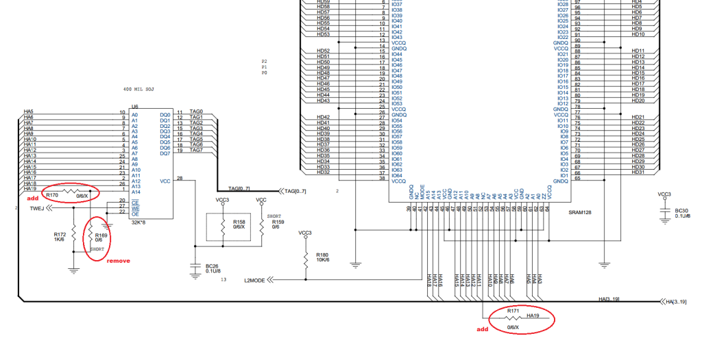
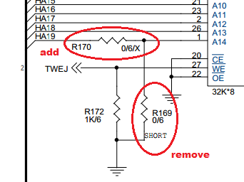
This schematic was posted by Roman555 on VOGONS and has been spread around quite a bit. Most think of it as a full summary for a “512K to 1MB Cache Mod”, but what does it mean?
- “add R170” – This connects the uppermost address line of the TAG ram chip.
- “remove R169” – This removes the fixed level of the uppermost address line from the TAG ram chip.
- “add R171” – This connects the uppermost address line to the actual cache chip.
This schematic makes the process seem simpler than it actually is. Firstly, you cannot know outright which of these signals and pins are exposed in an easy-to-solder way on your particular motherboard nor is it apparent which pads go to which signal.
Secondly, and most importantly, it omits the strapping arrangement that signals to the chipset what the installed cache size is.
On top of that, depending on your motherboard (spoiler: The GA-5AX is not one of them), software tweaks or BIOS modifications may have to be performed.
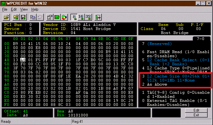
Cache Size Straps (HA20 / HA21)
The CPU address bus lines HA20 and HA21 are sampled by the chipset on boot to configure the detected cache size, according to the datasheet:
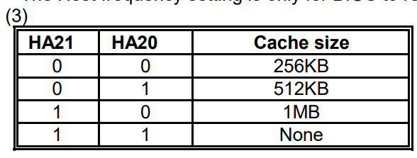
A configuration of a pull-up on HA21 and a pull-down on HA20 will set up the chipset for 1MB of cache.
Documenting Existing Hardware
First of all – let us see how we can translate this info to the GA-5AX. To figure this out, I armed myself with chip datasheets and a multimeter.
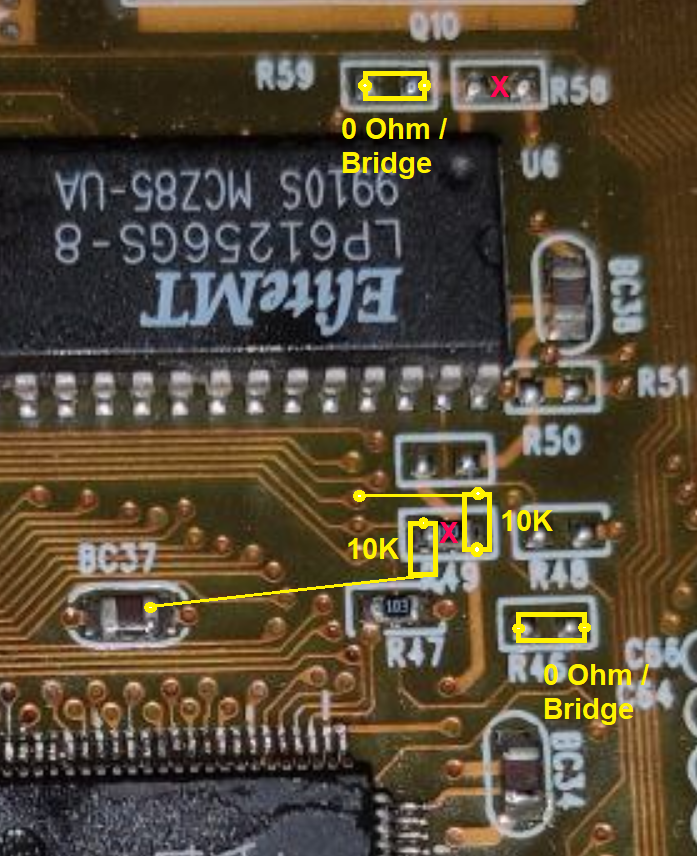
The following is an annotated photograph of the relevant area on the GA-5AX.
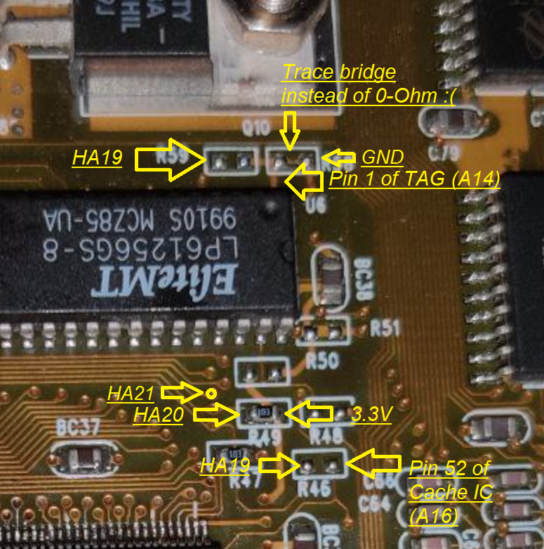
Here we can see where all the relevant signals are connected on the GA-5AX.
The cache chip that the board comes with is – in my case – an EliteMT LP61G6464AF-5, which is a 5ns 64K x 64 Pipeline Burst SRAM chip.
The 1MB variant is called LP61L64128F-4 (128K x 64, 4ns). The 4ns are an added bonus since this may potentially give us a tiny amount of overclocking headroom.
Assuming that we have managed to replace the cache chip without any damaged pads, cold joints or solder bridges, we may now continue with the modification.
The Extra Address Line
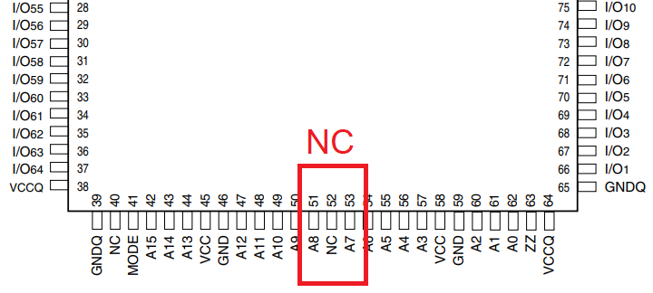
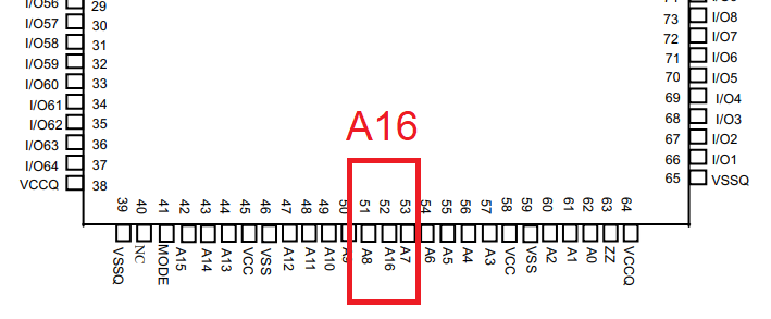
Since we double the cache size, Pin 52 on the cache chip, which is normally not connected, now assumes the role of an extra address line, A16. When using the chip as in a 512K configuration, it should be tied to VCC or GND. However, since we want to double the cache size, we must connect it to its destination (HA19 on the CPU address bus).
The unpopulated R46 on the board exists for this purpose, it needs to be filled with a 0-Ohm resistor or a bridge.
The same thing has to be done for the Cache IC. Pin 1 of the TAG chip now assumes the role of A14 and should also be connected to HA19 (side note – the numbers seemingly do not add up, this is because of different data widths between the different caches and buses – do not worry about it.)
As you can see here, A14 on the TAG can either be connected to HA19 via a 0-Ohm bridge (R170) or forced to GND (R169).
The GA-5AX ties this line to GND, which is correct for a 512K cache setup, however instead of using a 0-Ohm link as implied by the unpopulated R58, there is actually a copper trace connecting the two pads of it. This is obviously not ideal.
The trace between the two pads of R58 must be cut.
The unpopulated R59 must be filled with a 0-Ohm resistor or a solder bridge to connect the line to HA19.
Correctly Strapping HA21 / HA20 For 1MB
As written above, the two signals must be pulled to a logic 1 (HA21) and 0 (HA20) to tell the chipset that 1MB of cache is installed on the board.
This board relies on an existing pull-down for the strapping arrangement and only pulls HA20 to 3.3V in order to signal the 512K cache size. This makes things a bit tricky because we need to pull HA21 high in order to signal a 1M cache size and that pin is not easily available on a pad or pin, but it is available on a via closeby. The solder mask has to be scratched away to access it for soldering.
Then, a 10K Resistor must be connected between 3.3V and HA21.
The existing pad for HA20 must be pulled to GND via a 10K resistor.
Modification Summary
The following diagram sums up everything that needs to be done for this modification including the suggested locations for the signals. Yellow implies the addition of a line or component, red implies the removal of such.
Test Setup
The modification was performed and tested on the following setup:
- Gigabyte GA-5AX Revision 4.1
- Recap (with increased capacity values)
- Direct wire from ATX 3.3V to AGP 3.3V rail
- ALi M1541 Revision E Northbridge
- EliteMT LP61L64128F-4 1MB Cache IC
- AMD K6-II+/570ACZ
- Modified to K6-III+
- 110MHz FSB, 6.0x Multiplier
- 2.3V Core Voltage
- 128MB Hyundai SDRAM
- CL2-2-2-4
- Several M1541 Register Tweaks
- AGP driver 1.90 set to “Turbo” mode in ALi AGP utility 1.40
- ASUS GeForce 2 GTS
- 235 MHz Core Clock
- 390 MHz Memory Clock
- Driver version 7.76
- Silicon Image Sil3152 PCI SATA Controller
- Intenso 120GB SSD
- D-Link DFE-530TX PCI Fast Ethernet Adapter
- Windows 98 Second Edition
- 98Lite Sleek
- DirectX 8.1
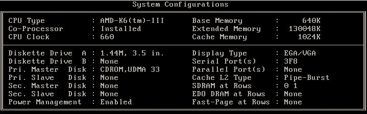
There was no BIOS modification necessary to get 1MB of Cache to work.

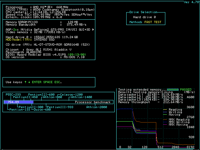
Performance & Conclusion

- 3DMark 2000 went from 5055 to 5235
- 3DMark 99 MAX went from 5614 to 5701
- 3DMark 2001 SE went from 1819 to 1877
- Unreal Timedemo gained around 1.5 FPS on average.
In total, you stand to gain about 1 to 5%, depending on the application. Was the modification worth it? From a learning standpoint I think ‘yes’, practically speaking ‘maybe’. After all, I did have to sacrifice a motherboard and the chips themselves are quite hard to find.
But… if you are going to start asking this question – why bother with this hobby? 🙂
Do not hesitate to reach out if you need help replicating this modification or doing other tweaks. See you next time!
– Eric
Special Thanks
- Tiido Priimägi for his help on pinouts and giving me general understanding of how caches and the individual signals work
- Roman555 for his original schematic on VOGONS
Thank you for the guide. Did this guide make Ram over 128mb cacheable?
I have an board with E revision.